800G & 1.6T Connection Guidelines
800G is now a foundational network speed for high-bandwidth data-center applications, including AI networking (AIN) fabrics that carry intensive east-west traffic between GPU and accelerator clusters, storage systems, and leaf-spine switches. It is also used across metro, long-haul, and Data Center Interconnect (DCI) networks.
As AI clusters scale and emerging 1.6T network layers move into deployment, automated fiber-cut simulation becomes critical for validating failover, path diversity, and service resilience under realistic physical-layer failure conditions.
What this guide covers
- 800G cabling options for connecting high-speed systems to Echola Fiber-Cut Switches and VOAs.
- Physical breakout requirements for common 800G optical architectures.
- Planning considerations for emerging 1.6T AI-networking and data-center links.
- Shared optical-equipment testbeds using Echola 1xN switches with Ixia and Spirent analyzers.
- Echola port counts required for documented bidirectional fiber-cut simulations.
800G Today, 1.6T Next
Modern AI infrastructure depends on high-bandwidth, low-latency links for scale-out GPU fabrics, distributed training, inference clusters, storage access, checkpoint movement, and inter-rack traffic. 800G provides the current high-speed foundation for many of these AIN applications, while 1.6T is emerging to support larger clusters and higher per-port bandwidth.
Echola Fiber-Cut Switches and VOAs allow network and system teams to introduce repeatable fiber cuts, attenuation events, and path disruptions so that redundancy, convergence behavior, and recovery can be verified before deployment. The required Echola port count is determined by the physical Tx/Rx paths exposed by the selected optical module and breakout architecture.
800G Cabling Architectures
Detailed port mapping below applies to the documented 800G breakouts.
800G 2xLR4
Dual-Channel WDM
This architecture acts as two independent 400G LR4 lines inside a single 800G shell. It multiplexes four wavelengths per channel over parallel paths and is designed to break out one 800G port into two separate 400G pathways.
Transceiver examples
- Cisco/Arista-compatible 800GBASE-2LR4 OSFP/QSFP-DD using Dual Duplex LC.
- Approved Networks 800G QSFP-DD 2xLR4 transceiver.
Corresponding cable
Dual Duplex LC Single-Mode Breakout/Patch Cable.
This is a physical fiber split. It plugs into the two physical dual ports on the transceiver and separates them into two standard single-mode Duplex LC lines on the Echola end.
800G PLR8 / LR8
Parallel Optics
This architecture uses parallel optics, driving eight distinct data lanes down eight separate physical pairs of single-mode fiber without internal wavelength multiplexing inside the transceiver.
Transceiver examples
- FS.com QDD-PLR8-800G QSFP-DD module for up to 10 km over eight single-mode pairs.
- NADDOD 800G OSFP PLR8 / DR8 with high-density MPO-16 connection blocks.
Corresponding cable
MPO-16 APC Female to 8x LC Duplex Single-Mode OS2 Harness/Breakout Cable.
The MPO-16/APC end plugs into the 800G PLR8 transceiver, then fans out into eight independent Duplex LC legs that match the standard LC ports on the Echola chassis.
800G Port Count Summary
| 800G Architecture | Optical Format | Cable / Breakout Type | Echola Ports Required | Use Case Notes |
|---|---|---|---|---|
| 800G 2xLR4 | Dual-channel WDM | Dual Duplex LC single-mode breakout / patch cable | 4 ports | Two 400G LR4 legs; 2 ports per leg for Tx/Rx bidirectional testing. |
| 800G PLR8 / LR8 | Parallel optics | MPO-16 APC Female to 8x LC Duplex Single-Mode OS2 harness | 16 ports | Eight Tx strands and eight Rx strands routed through the Echola switch. |
Optical Equipment-Sharing Testbeds
High-speed Ixia and Spirent traffic generators and analyzers represent a significant capital investment, especially when test environments must support 800G and emerging 1.6T interfaces. Echola 1xN optical switches can place this equipment at the center of a shared testbed and route its optical connection to multiple devices under test, racks, or engineering stations.
Instead of dedicating an analyzer to every test setup or repeatedly moving fiber connections by hand, teams can remotely select the required optical path. This improves analyzer utilization, reduces manual patching and connector wear, and makes repeatable regression, interoperability, qualification, and failure-recovery testing easier to automate.
Example shared topology
↓
Echola 1xN Optical Switch
↓
Multiple 800G / 1.6T DUTs or Testbeds
- Share one analyzer across multiple labs, racks, or DUTs.
- Switch test paths remotely without disturbing the fiber plant.
- Automate scheduled, overnight, and regression-test workflows.
- Combine path selection with fiber-cut and attenuation testing.
Map the Physical Breakout
A 1.6T interface may be deployed as a native 1.6T optical link or broken out into lower-rate links, such as 2x800G or 4x400G, depending on the switch, transceiver, connector, and media implementation. Because these physical architectures are not interchangeable, there is no single universal Echola port count for every 1.6T connection.
Before selecting a Fiber-Cut Switch, identify the transceiver standard, connector type, number of exposed optical Tx/Rx paths, and whether the link must be interrupted as one service or as independent breakout channels. Echola can then map the 1.6T design to the appropriate switch and VOA configuration.
Example 800G 2xLR4 Connection Setup for VFC/FC series switches
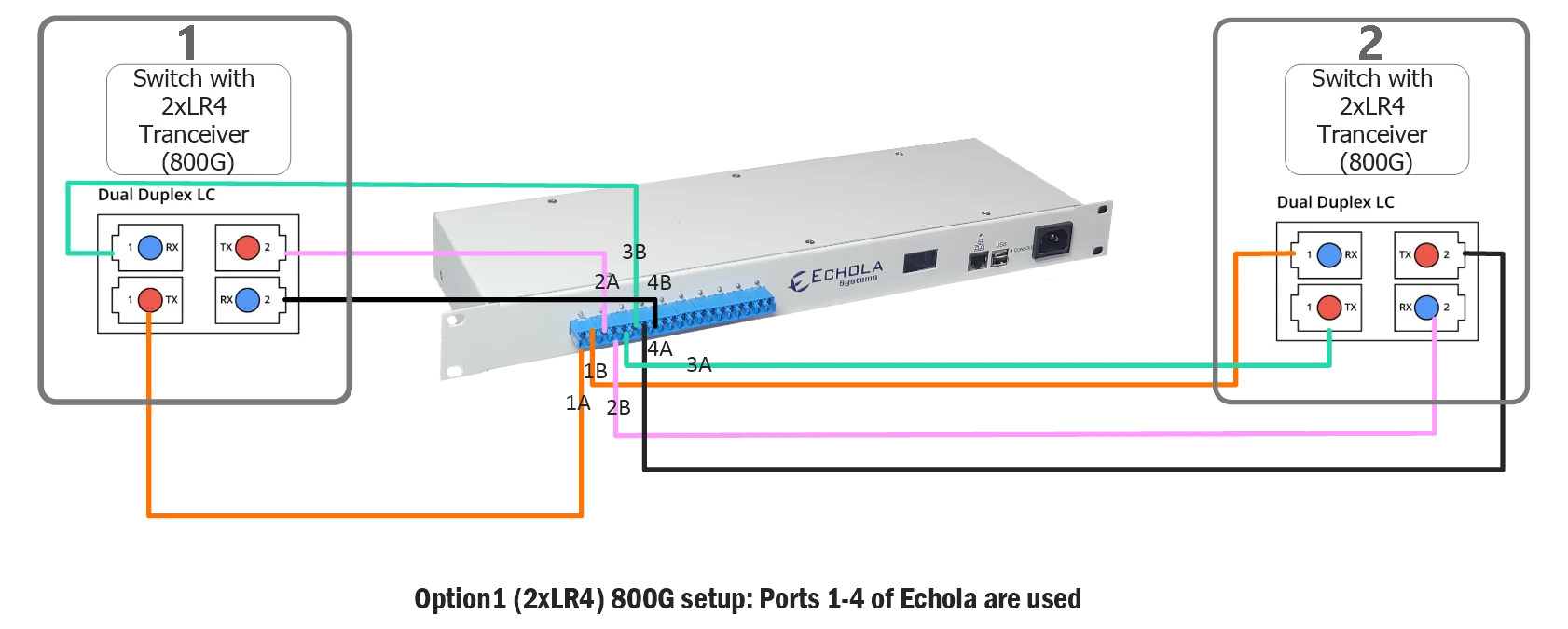
Example 2xLR4 800G setup showing Echola FC/VFC series ports 1–4 used for the bidirectional breakout connection.
Selecting the Right Echola Switch
For 800G 2xLR4 links, a 10-port Echola model can support the required four-port connection. For 800G PLR8 / LR8 links, use a 20-port model such as the VFC2011-SM so the full 16-port parallel fabric can be routed through the switch.
For 1.6T AI-networking and data-center links, switch selection must be based on the actual optical breakout and the total number of Tx/Rx paths that must be interrupted or attenuated. For shared Ixia or Spirent testbeds, Echola 1xN switch sizing should also account for the number of DUTs, bidirectional paths, connector types, and whether fiber-cut or VOA functions are required.